
While this limitation applies both to the switch and the router, we need to consider that the cost per-port on a router is much higher than on a switch. However, this technique has a serious limitation: the number of physical interfaces. With this approach, the router does not know about VLANs, it just treats everything as a different link. This way, a router receives a frame onto an interface, which is in a VLAN, and put it onto another interface (different VLAN). Specifically, we needed a cable going from the switch to the router for every single VLAN. In the past, we needed more than a single cable. Since we connect the router to the Switch with a single cable, this approach gained the name of “Router on a Stick”. With this technology, we need a router to perform Inter-VLAN routing. We have many technologies to perform Inter-VLAN Routing, and Router on a Stick is just one of them. Then, the packet is delivered to the correct device in the new VLAN. When the router receives a packet from a VLAN, destined to another, it just performs the Frame Rewrite task and pushes back into the switch. The router, instead, knows about all the existing VLANs, as they are all present in its routing table. Therefore, that device will contact its default gateway (the router) when trying to reach those devices. It does not know they are on another VLAN on the same switch, it just knows they are on a remote subnet. If all those segments are VLANs, then we are talking about Inter-VLAN routing.įor a device inside a VLAN, devices in another VLAN are just away. Since routers have several interfaces with an IP address, all on different network segments, they allow communication between these segments. Instead, it simply is the way we label a process routers normally do. Inter-VLAN routing is not a specific technology or implementation. Explaining Inter-VLAN Routingīefore we start the configuration, we may want to pause to completely understand what we are going to do. VLAN IDįor each client (PC), the default gateway is the IP address of RoaS in the same VLAN as the client. Use the following tables to understand all the configuration items we are going to work with. In the end, we will take a minute to analyze the routing table and check how the router works for this specific task. Once this is 100% clear, we will move to the configuration part, going very fast on the Layer 2 side we already know about.

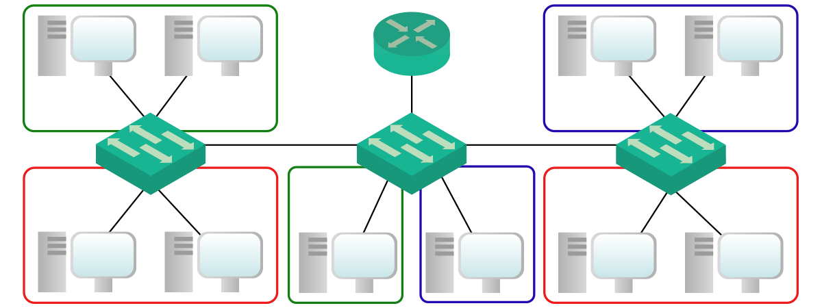
Configure “RoaS” Router to do Inter-VLAN Routing for the three VLANs previously createdīefore we start the configuration, we will present to you the logic of Inter-VLAN routing using a router.Configure access ports and trunks according to the tables below.Create three different VLANs with IDs 10, 20 and 35, named respectively “Red”, “Blue” and “Green”.To be more specific, here’s what we need to do. Consequently, you will need to configure the VLAN part, including trunks, and the Inter-VLAN routing part. However, all network devices are with factory configuration (we just changed the hostname). We already configured for you all 10 PCs with IP address, subnet mask, and default gateway. If you open the Packet Tracer, you’ll see we called this device just “RoaS”. Therefore, all traffic that has to go from a VLAN to another, will flow through this router.

In case it wasn’t clear, the only router in the picture is the one we will use for Inter-VLAN routing. This is the topology for this lab, the colored squares represent the VLANs.


 0 kommentar(er)
